RANDOM PAGE
SITE SEARCH
LOG
IN
SIGN UP
HELP
To gain access to revision questions, please sign up and log in.
A2
The Bus
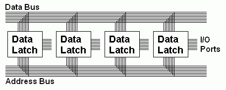
This is a collection of wires (often 4, 8, 16, 32, 64 or 128). These wires are used to interconnect all the devices within a computer. This approach greatly reduces the complexity and amount of wiring needed. Many devices share the same bus instead of each device having its own wiring. To make this work, tristate logic is needed.
Tristate Logic
- allows two or more devices to share/write to the same bus line.
- has three output states: Zero, One and Disconnected (high impedance).
- has a control line usually called enable or chip enable. This makes the output active.
- responds to one unique address provided on the address bus. This could be a memory location or an I/O location.
- There is a control bus line that selects memory mapping or I/O mapping allowing the same addresses to be used for either. This still guarantees that one and only one device is ever avtive.

Tristate Logic used for BUS Sharing
- Only one tristate device can use the bus at any time.
- The processor controls which device has access to the bus by setting the address on the address bus.
- The devices not using the bus are disconnected. Their outputs are set to have a high impedance.
- Tristate devices respond to a unique address on the address bus.
Tristate Buffer
- A buffer copies its input to its output.
- There is usually a smaller input power and enough output power to drive multiple devices.
- Tristate buffers have three states; 1/On, 0/Off and Disconnected / Floating.
- A chip-enable pin is used to activate the device.
- When ON, the output sends 5 volts onto the output line.
- When OFF, the output sends 0 volts onto the output line.
- When disconnected, other devices can share/use the same data bus line.
- When disconnected, it is still wired up but the output resistance is very high so the device behaves as though it is disconnected. This state is also known as "floating".
Bus Contention
- Two or more devices might want to write to the bus at the same time.
- This is never allowed.
- Think of this as electronics arm-wrestling.
Microcontroller I/O Ports
- These can be inputs or outputs.
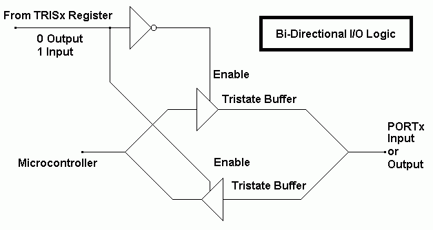
- The TRISx registers determine whether each I/O line is an input or output.
This is the circuit showing two tristate buffers. Only one is ever active. In this way data can flow in or out but never at the same time.

reviseOmatic V3
Contacts, ©, Cookies, Data Protection and Disclaimers
Hosted at linode.com, London


